


We are willing to make a useful thing for the technical community by exposing some basic theory about the world in which we are operating. For this purpose, we set this section of our Website which we intend to enrich progressively.
Our intention is to help rotating equipment engineers operating with EPC contractors, End Users, Service companies, Public administration but also Engineering students and other people potentially interested in our machinery and on how it can be improved to help achieving a better environment.
Those who find interesting the technical material reported in this section of our website and want to go deeper in the various subjects may ask the expert to have more more specific information.We hope you enjoy reading our “Theory at a glance”.
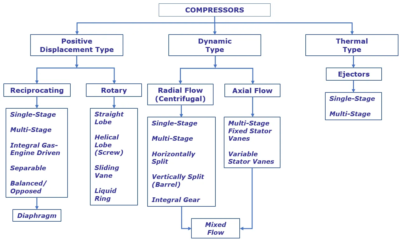
Several different types of compressors were developed along the history of technology and are nowadays employed for different environments and applications.
The following figure shows the various types of compressors available.
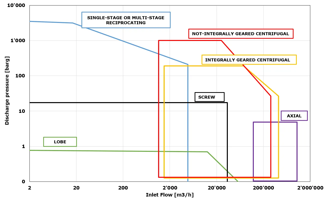
Centrifugal compressors are dynamic machines with a wide range of applications (Oil&Gas up/mid/down-stream, natural gas processing, refrigeration, technical gas, air, etc.), working with any compressible fluid, either gas or vapor, having wide range of molecular weight, even if, when the molecular weight is lower, also the amount of pressure the centrifugal compressor can generate is lower. As it can be seen from the previous figure, centrifugal compressors range in volumetric size from few thousands to 3÷4 hundred thousand m3/h. At lower capacities they have problems competing with other more efficient volumetric compressors available; at higher capacities axial compressors perform better. Inlet pressure level can be any value from a deep vacuum to a high positive pressure. Pressure ratios and pressure levels are difficult to describe in general terms because of the wide range of applications. Depending on compressor type, number of thermodynamic sections, type of gas and application, total pressure ratios can range from less than 2 up to about 200. Discharge pressure can range from sub-atmospheric levels up to 800÷1000 bar.
A centrifugal compressor is an operating turbomachinery in which one or more rotating impellers supply dynamic energy to a compressible fluid with the aim to increase its pressure.
When the inlet nozzle is not axial, an inlet volute is necessary to convey the gas into an annular stream to feed the (first) impeller. Leaving the impeller with an increased velocity and increased static pressure, the gas enters the diffuser (vaned or vaneless), where part of the velocity is converted into static pressure. A return channel (“U” shaped and vaned) is needed to bring the gas in front of the next impeller when more compression stages are provided in line. The discharge system usually makes use of a discharge volute, aimed to convey the gas to the outlet nozzle, possibly with an additional conversion of kinetic energy into static pressure.
The impeller consists of a set of vanes radially oriented on a hub, rotating at high speed, driven by the shaft. Usually, the rear shroud is attached to the vanes and rotates as a part of the impeller assembly; if the front shroud is stationary, the impeller is referred to as semi-open, while if the front shroud is attached to the vanes and rotates with the assembly, it is referred to as closed. The term open impeller refers to the case (more theoretical than real) in which both front and rear shroud are stationary.
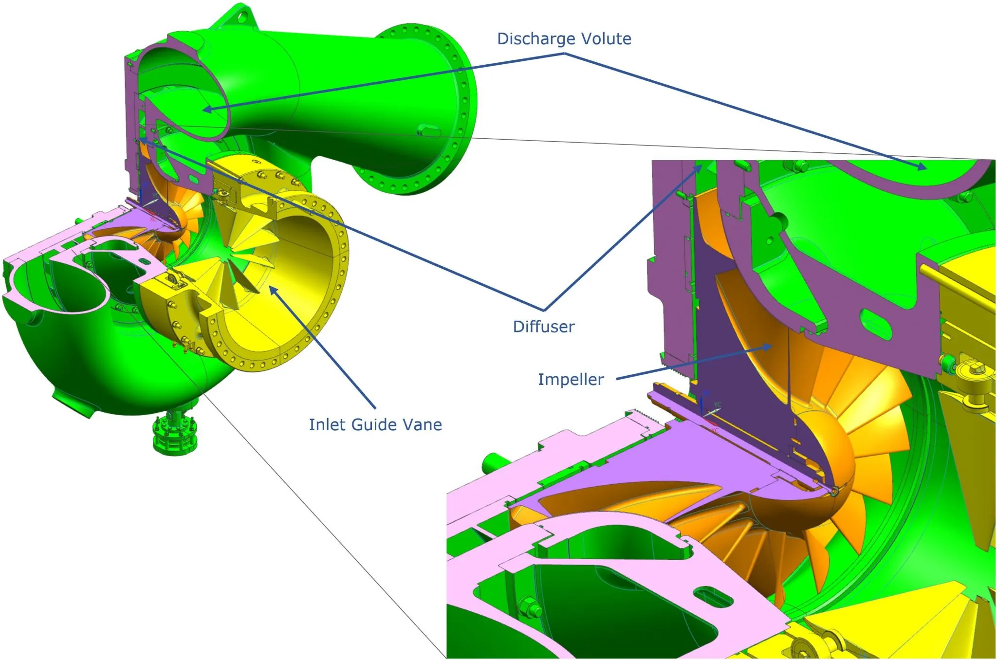
The diffuser can be vaneless or bladed. In the second case the blades can be low-solidity or high-solidity type; the vanes have inner edge in line with the direction of the resultant airflow from the impeller and diverge, to convert the velocity head into pressure energy.
Inlet guide vanes (IGV) are used to control the capacity, changing the angle of the gas flow into the eye of the first impeller.
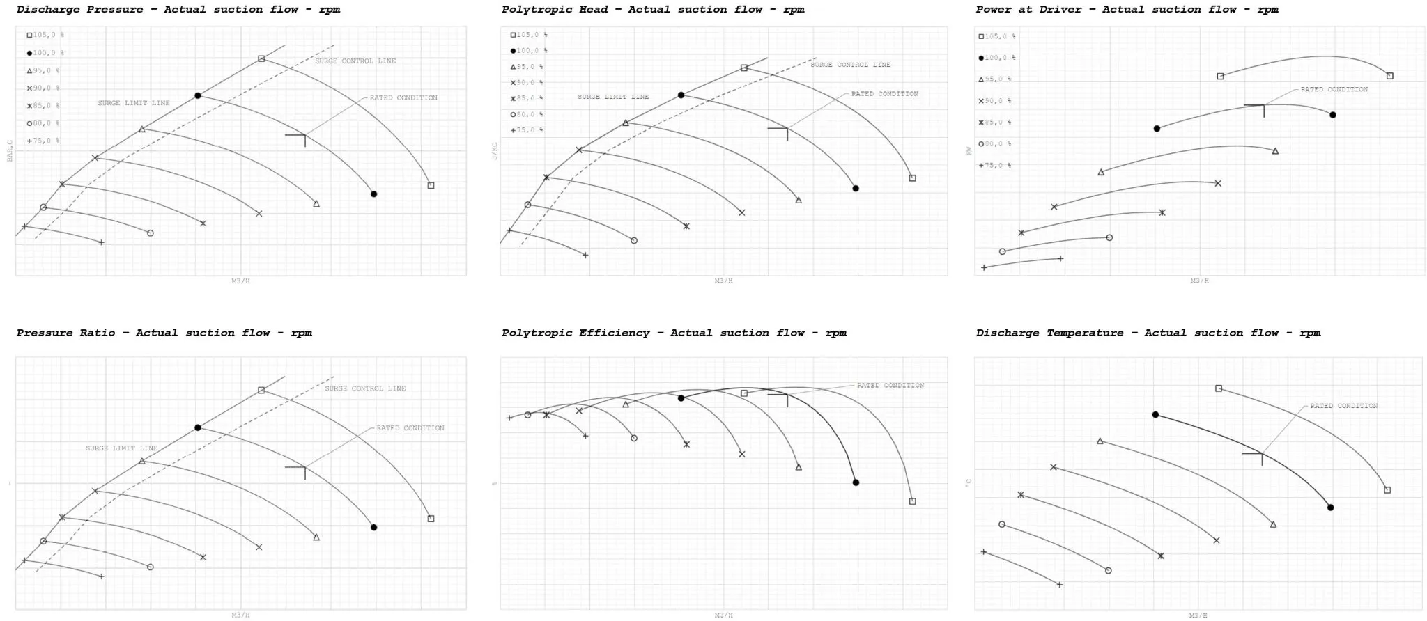
Centrifugal compressor performance can be expressed in non-dimensional form in terms of head coefficient, flow coefficient and efficiency. Such non-dimensional performance curves can be defined by the designer in standard operating conditions, and then used to size the compressor for a specific application after a proper scaling of dimension considering different gas handled and compressor speed.
The head coefficient relates the head to the tip speed of the impeller, or, in other terms, the specific work of compression to the specific kinetic energy of the gas: it is therefore the dimensionless specific work for a compression stage.
The flow coefficient relates the velocity of the gas to the speed of the impeller. Since the gas velocity is related to the volume flow entering the impeller surface, the flow coefficient is considered as a dimensionless suction volume flow.
The compression efficiency can be referred to the polytropic or isentropic transformations (usually the first one).Relationships between efficiency and flow coefficient, as well as, between the head coefficient and flow coefficient for a given stage and/or the whole compressor can be plotted as dimensionless performance maps. Such performance curves can be used for predicting compressor performance.
Compression stages are designed on a specific flow coefficient at the maximum efficiency but can operate in a range limited by surge and choke conditions. When the compressor operates at flow rates different from the design, the efficiency decreases.
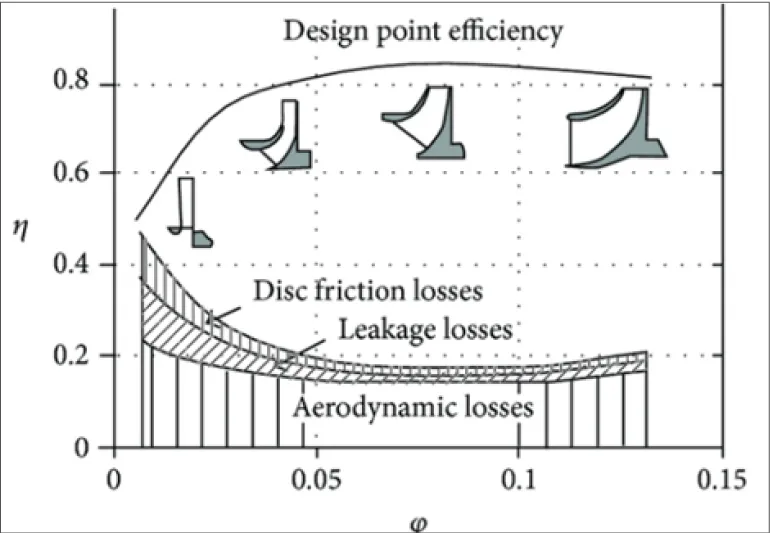
Based on the selected design flow coefficient, it is possible to define several kinds of impeller geometries: from 2D up to the axial ones. The flow coefficient is in fact the most important factor for the selection of the impeller type. Indeed, a small value of the flow coefficient implies small inlet and exit areas, i.e. narrow axial inlet and exit widths. The lower flow coefficients correspond to shrouded, two dimensional impeller geometry. Its lower limit is dictated by a dramatic increase of the friction loss at the flow channel walls due to the reduction of the hydraulic diameter and consequently a breakdown of efficiency and head. As the flow coefficient increases, both the inlet and outlet section areas increase, inflow became axial implying 3D geometry. When the volume flow overcomes 3D centrifugal impeller limit, axial compressor has to be used.
The impeller vanes may be forward curved, radial, or backward curved, but the former are normally used in fans or blowers, and rarely, if ever, in centrifugal compressors.
At the impeller, in adiabatic conditions per mass unit of flow, at the inlet (point 1) and at the outlet (point 2) of the impeller the flow has energy content given by:
POINT 1 ENERGY CONTENT:
H1=h1+½c12
POINT 2 ENERGY CONTENT:
H2=h2+½c22
WHERE:
H = energy content of the gas flow;
h = enthalpy (static pressure) per mass unit;
c = fluid absolute velocity
(½ c2^2=kineticenergy per mass unit)
H12=H2−H1=h2−h1+½(c22−c12)
In the diffuser, after leaving the impeller, the velocity of the fluid decreases, changing kinetic energy into static energy. At the end of the diffuser (point 3) the energy content is:
POINT 3 ENERGY CONTENT:
H3=h3+½c32
BUT, SINCE NO ENERGY HAS BEEN TRANSFERRED PASSING FROM POINT 2 TO POINT 3, IT IS:
h3=h2+½(c22–c32)
As per the velocity triangle, the gas enters the impeller axially at speed c1 and is vectorially added to the peripheral speed u1=r1⋅ω giving the resulting relative velocity w1.At the impeller outlet, the gas (ideally) exits tangentially to the blading profile with relative velocity w2 and resulting absolute velocity c2 (being u2 the peripheral speed of the rotor).Using backwards bended blades, with the same flow rate (proportional to w2r) and the same peripheral speed of the impeller (u2) with respect to radial or forward bended blades, the absolute speed (c2) is lower. Lower is also the energy transferred to the fluid and the losses in the diffuser.
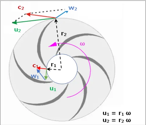
VELOCITY TRIANGLES ACROSS THE IMPELLER
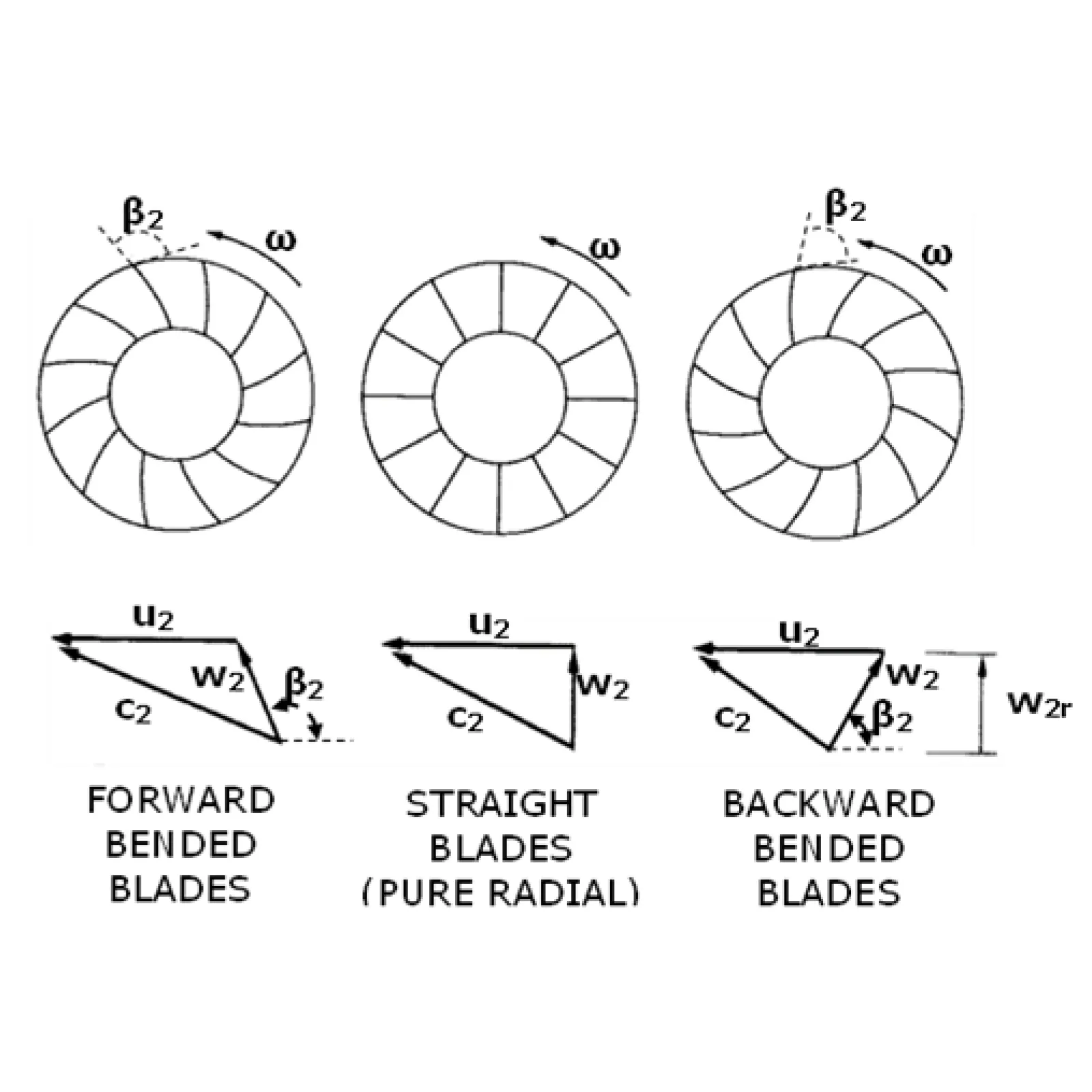
BENDING EFFECT OF THE EXIT BORDER FROM THE IMPELLER BLADING
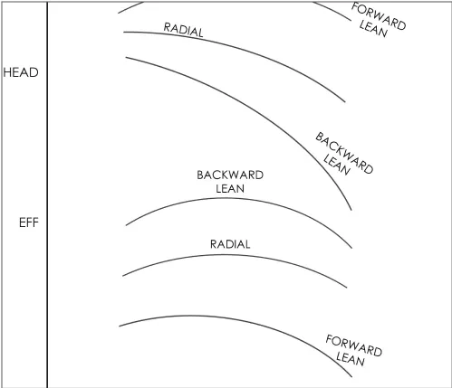
EFFECT OF IMPELLER BLADE ANGLE ON COMPRESSOR HEAD AND EFFICIENCY
Not-Integrally Geared
Integrally Geared Compressors (IGC),
depending on the absence or presence of an integral gear.
The former are certainly the workhorses operating in most of the industrial processes such as gas transportation, chemical, petrochemical, refinery, pulp & paper processes, while the latter have had a more recent development and market penetration, with an established tradition in few typical applications such as air separation, vapor extraction, CO2, refrigeration, steam compression, process, and plant air (they can also be used for the simultaneous processing of different gases and with expander stages for energy recovery).
For most of the process applications the reference Standard for Centrifugal compressors is the API 617, which specifies many recommended practices and design principles.
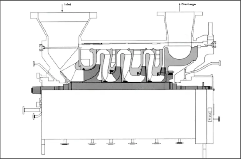
Not-Integrally Geared Compressor (API 617 chapter 2) are typically multiple stage machines where impellers are installed in one frame between bearings and operate in series. The compression stage consists of the inlet system (only for the first stage, sometimes including Inlet Guide Vanes), the impeller, the diffuser, and a return channel to the subsequent stage, or a discharge volute after the last stage. All the impellers are located between the bearings, hence they can be named “Between Bearing Compressor”. Also, single stage compressors with overhung impeller and axial inlet belong to this category; the shaft is directly coupled to the driver and the stage is on the opposite drive side end.
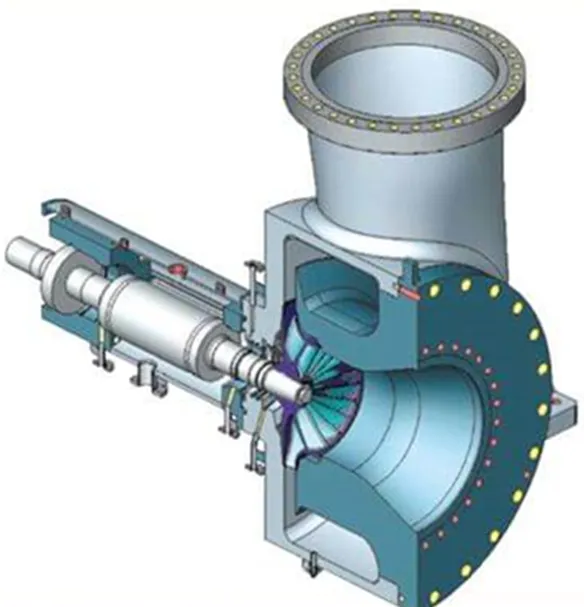
SINGLE STAGE OVERHUNG IMPELLER COMPRESSOR
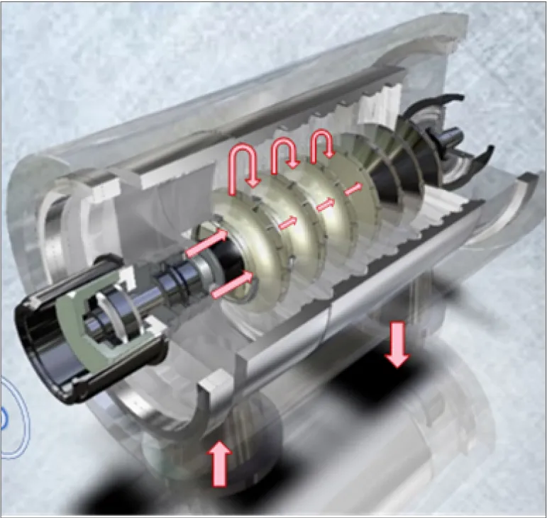
TYPICAL COMPRESSOR WITH IMPELLERS BETWEEN BEARINGS: FLOW PATH
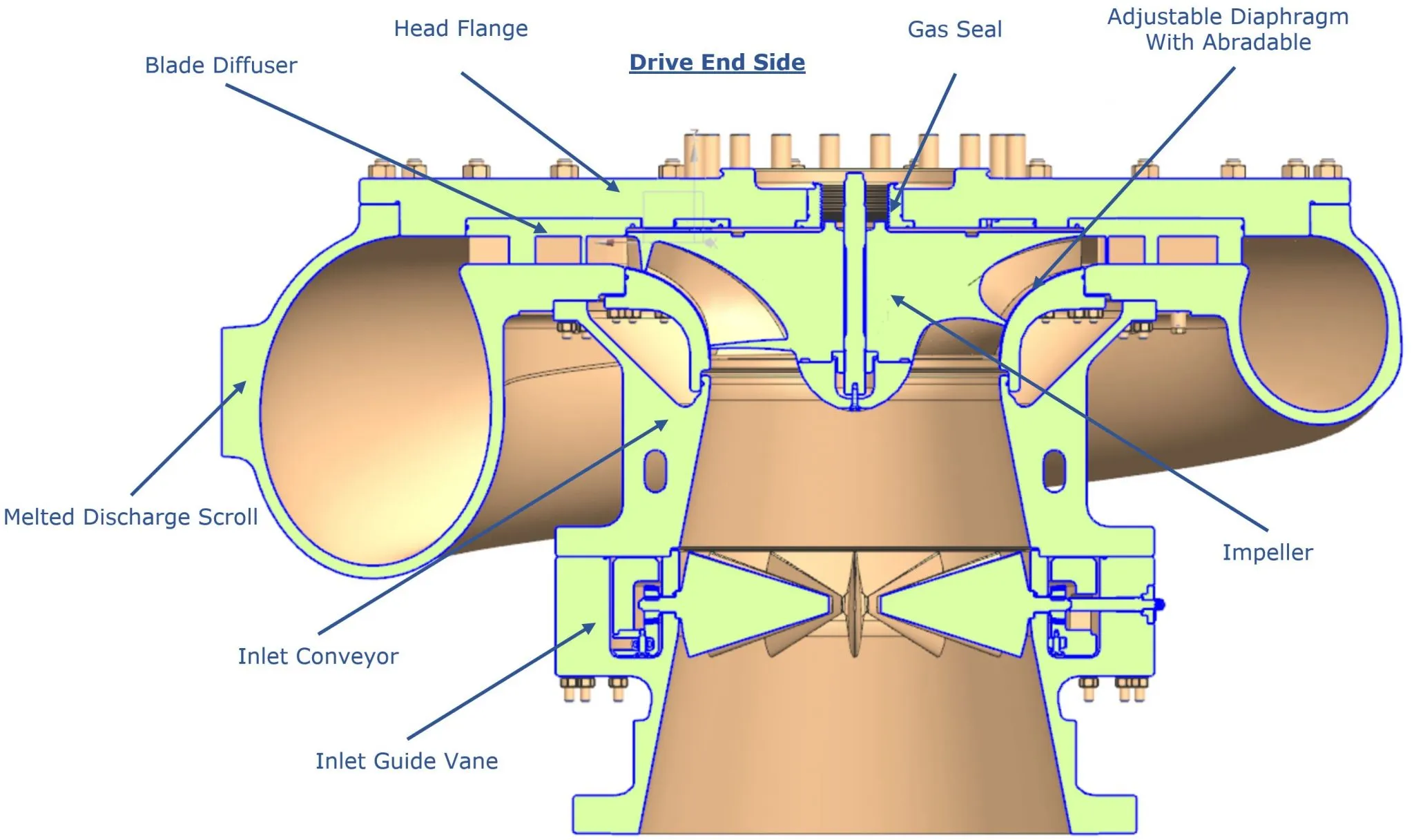
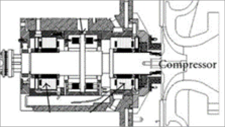
Integrally Geared Compressor (API 617 chapter 3) are typically multiple stage machines where the driver is coupled to the bull gear driving 1 or more high speed pinions (up to 5), each one with one or two overhung impellers at the opposite ends. Each shaft rotational speed is defined to optimize the impellers performance. The compression stages include often Inlet Guide Vane and always conveyor, impeller, diffuser, volute, and outlet pipe.
API 672 Standards are also applicable for Integrally Geared Centrifugal Compressors packages (preassembled on a skid) for air service.
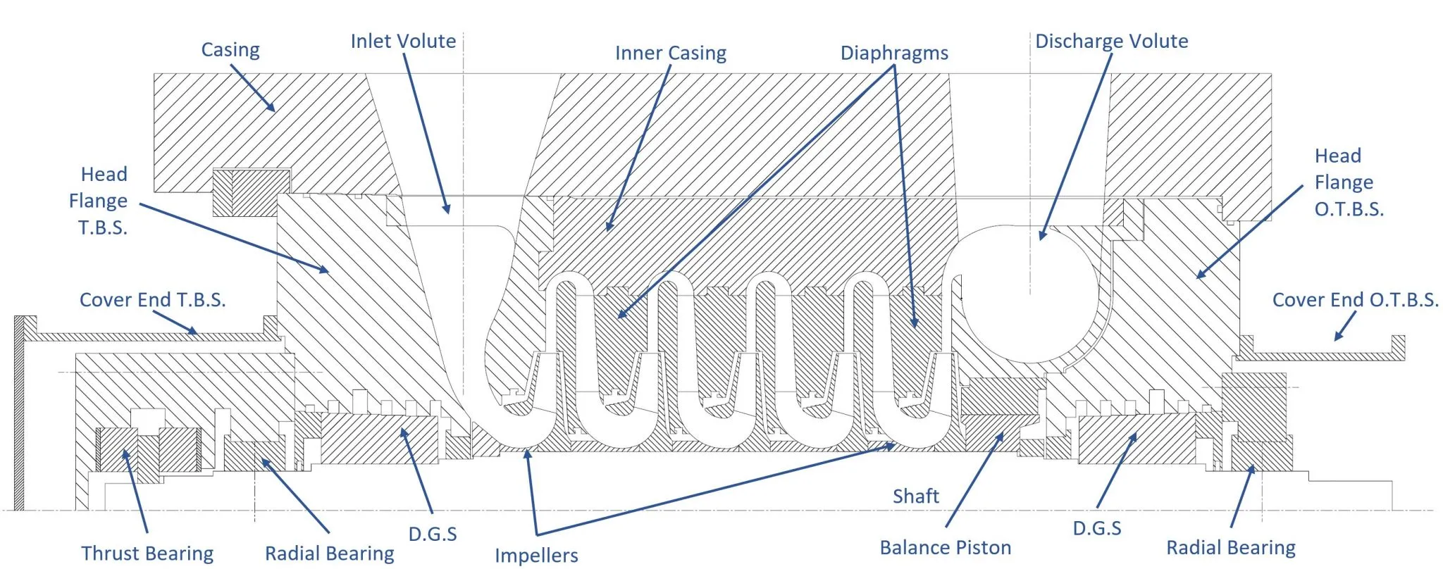
Traditional “Between Bearings Compressors” (belonging to Not-Integrally Geared category) are composed by an external casing containing up to 3 sections, each one with one or more compression stage (up to 10 in total). For each stage an impeller is mounted on the single rotating shaft and the whole rotating assembly is named rotor.
A section includes the set of consecutive stages that do not have inter-refrigeration or side stream injections/extractions of the processed fluid. Each section includes conveyor, inlet volute and several stages with impeller, diffuser and return channel, up to the last one including impeller, diffuser, outlet volute and outlet pipe. The rotating part of the compressor consists of the impeller(s) and the shaft. This rotor runs on two radial bearings (on all modern compressors, these are hydrodynamic tilt pad bearings). A balance piston is generally provided to reduce the axial thrust generated by the impellers. A hydrodynamic tilt pad thrust bearing is used to balance the residual axial thrust.
Some processes require compression trains with several (up to 4) casings. The casings can have different arrangement of the sections:
•Straight Through (suction of the following section adjacent to the discharge of the previous one) with side stream, if necessary
•Back-To-Back (adjacent sections discharge)
•Double Flow (two sections in back-to-back arrangement, working in parallel)
STRAIGHT-THROUGH
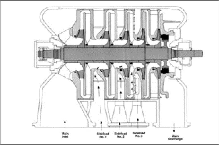
STRAIGHT-THROUGH WITH SIDE STREAMS
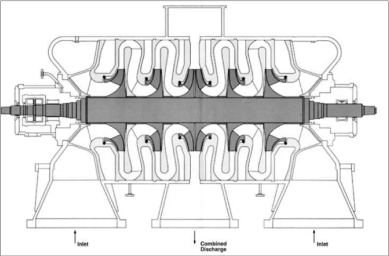
DOUBLE FLOW
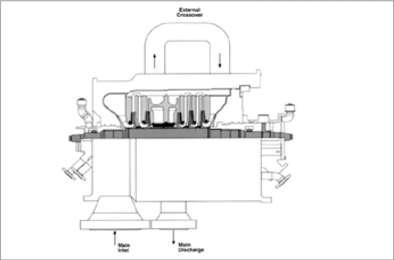
BACK-TO-BACK
•Horizontally Split Compressors
•Vertically Split Compressors
As it will be explained in the following paragraph, the choice of the external casing layout (with its advantages and disadvantages) remarkably affects maintenance operations.
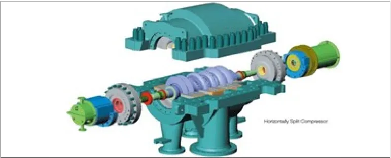
HORIZONTALLY SPLIT COMPRESSOR
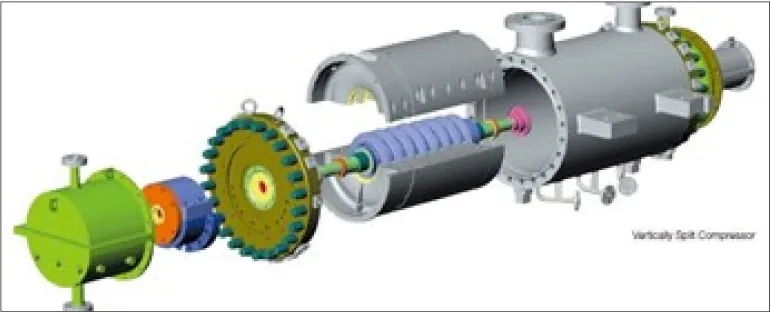
VERTICALLY SPLIT COMPRESSOR
Maintenance of the horizontally split compressor is very simple, as, after removing the top half casing, the rotor can be removed without disassembling the impellers and then bearings and seals are readily accessible for inspection and repairs. Of course, unless the process connections are placed in the bottom half (as commonly it happens in case of condensing Steam turbine driving), they must be removed before opening the case. Horizontally split casings are usually applied for discharge pressure up to 40-60 bar.
When the pressure is higher, or the molecular weight is too low, vertically split (“barrel type”) compressors are used to avoid gas leakage from the two casing halves of horizontally split compressor. In this case the complete bundle (rotor and split diaphragms) must be removed for maintenance to access the rotor; adequate space is necessary for this operation (also removing of additional casing opposite driver side, if any) but no need to remove the inlet and outlet flanges.
Vertical split compressor used for high pressures, can also have bell shaped casing, with a single vertical end cover, closed with shear rings instead of bolts.
Special arrangements is used for Pipeline Compressors, used for natural gas transportation: normally they have side suction and delivery nozzles positioned opposite each other to facilitate installation on gas pipelines. Axial inlet is also available when the pressure ratio allows for a single impeller.
The maximum number of impellers (up to 10) in Between-Bearings compressor casings is usually limited by rotor-dynamic considerations. Therefore, the maximum amount of head to be generated in one casing is limited. If more head is required, multiple casings, driven either by the same driver or by separate drivers, must be used.
Integrally Geared Compressors are composed by one or more stages, each one including conveyor, impeller, diffuser, volute, and outlet pipe. They are usually inter-refrigerated, being frequently the intercoolers included as part of the machine package. The casing is also attached to the gear box, which is connected to the foundations, the bull gear is connected to the driver by means of a coupling.
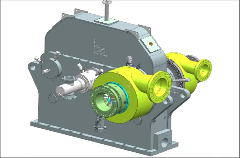
TYPICAL INTEGRALLY GEARED COMPRESSOR
Same compression stage arrangement is adopted also for single stage compressors with overhung impeller (even if they are Not-Integrally Geared).
Usually, overhung compressors do not permit the removal of the rotor without first removing the impeller.
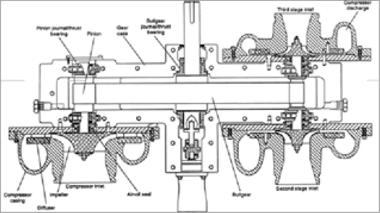
INTEGRALLY GEARED COMPRESSOR ARRANGEMENT
OVERHUNG IMPELLER COMPRESSOR
A limitation to the head may be the temperature limits of the compressor; typically, the discharge temperatures are limited to about 200° C.
If more head is required, the gas must be cooled during the compression process.
•up to three compressor casings (Between-Bearings type) can be coupled with the same driver (having one or two driving shaft ends), with one or more gearboxes, if necessary
•integrally geared compressor type with multiple pinions, usually one section for each stage
•rarely, also hybrid solution of the above mentioned casesSEALS
Seals are used to keep the gas from escaping through the bearings: so, both shaft ends are to be sealed for Between-Bearing compressors and each shaft end close to an overhung impeller. Except for applications in air or nitrogen compression, where often carbon ring seals or labyrinth seals are used, nowadays all centrifugal compressors use dry gas seals (DGS).
For dry gas seals, the sealing is accomplished by a stationary and a rotating disk, with a very small gap (about 5µm) between them. At standstill, springs press the movable seal disk onto the stationary disk. Once the compressor shaft starts to rotate, the groove pattern on one of the disks causes a separating force, making the seals run without mechanical contact of sealing surfaces. Four different arrangements are possible for DGS: single, double, tandem, tandem with intermediate labyrinth; the last one being applied in the most of applications.
At present, high speed compressor rotors (both “Integrally Geared” and not) are generally equipped with tilting pad bearings (2 Journal and 1 Thrust), since they are the most suitable for stability reasons (capability to resist any unbalancing action of the oil film), while low speed compressor shafts (for instance: bull gear shaft of “Integrally Geared” compressors) are equipped with fixed geometry bearings (for instance, 2 Journal plain type and 1 Thrust tapered land type).
